So I thought I'd do some brief post about different ways of powering your project, the pro's and con's of each type and off the self solutions I would recommend for the new electronics hobbyist.
First off:
Linear Regulated Supplies
Linear supplies means the unregulated DC input to the regulator is - well - regulated to a stable constant voltage, without using any switching action, providing the input to the regulator is greater than that of the output.
A definition of an unregulated supply: the output of a rectifier, a battery, alternator or generator output - all of these will have a voltage but will not be constant over time.
A definition of an unregulated supply: the output of a rectifier, a battery, alternator or generator output - all of these will have a voltage but will not be constant over time.
A voltage Regulator can be analogous to a regulator on a divers air supply. The pressure in the tank is far greater than the diver would need to take a breath, otherwise it would blow their lungs! so the pressure regulator reduces the pressure to something sensible so the diver can take a breath without turning into a balloon! Likewise if the pressure in tank is lower than the pressure outside, no air will flow out of the tank (bear this in mind)
Why Linear
- They are cheaper than Switch mode
- less noisy - no switching frequency to be coupled onto the supply
- simple
- no inductive components
Why not linear
- not very efficient - lots of power loss
- very hard to handle high currents (as above), without having to add more components
- not very good for battery applications (except maybe LDO's)
Cheap and Easy
The simplest linear regulator is a resistor-Zener network:

I don't particularly like using these, but they are stupidly simple, uber cheap and zeners and resistors are always available. However you must check the Iz for your zener as incorrectly calculating R will mean your zener will not behave to spec. Usually the physical size of a zener can dictate how much power the circuit can handle. For low power, cheap and easy applications, this one is a winner.
if you can't be bothered working out the values, then this online calculator takes the leg work out of it.
A Little more refined
A better way of regulating your supply is to use a voltage regulator:

This is a typical circuit for one. It does look more complex than the Resistor Zener network, but its pretty elementary: the op-amp basically drives the transistor till its inputs are equally balanced. The inverting input in this case is connected to a resistor zener network as before, but only this time there is no load current (assuming infinite input impedance one the op-amp). When the voltage at the non-inverting input reaches the same as that of Vref, the op-amp stops driving the transistor, till the supply drops. the process is very quick and linear. However you don't have to build this circuit each time as it comes in neat, cheap little packages.
A typical regulator circuit is shown below:
 |
Linear regulators are the easiest to implement. Take the humble 78xx (where xx is the voltage it regulates the output at) series of voltage regulators: these come in the common TO-220 package (for beefier application) or TO-92 (for lower power applications, Usually noted by the L suffix):
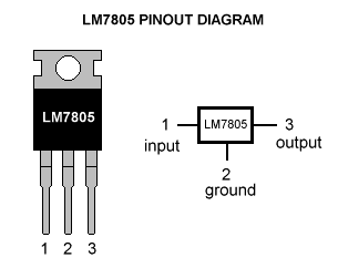 |
| TO-220 package 7805 (+5V) with pinout |
 |
| TO-92 78L05, similar package to that of transistors, with associated pin out. |
The 78xx series is the most common, cheap and readily available type of voltage regulator, so a good place to start for a simple DC-DC step down, but there a few things to consider:
Considerations
- As with the diver air-tank analogy: the input voltage must be greater than the regulated voltage.
- All linear voltage regulators have something called Vdo or Vdrop (or the drop out voltage). This is voltage drop across the regulators output to input. If you have a 12V-ish input and the output of your regulator is 5V (7805) then your Vdo = 12v - 5v = 7V.
- If you look at the datasheet for a 78 series regulator, You will find that the minimum drop voltage is 2V - so for a 5V regulator you MUST have a minimum input voltage of 7V
- With Vdo in mind you must also think about the power dissipated in the regulator itself
- So say you building a USB charger for your car using a 7805 (which is a valid design) so you require a current of 500mA max on the 5V output, and your input voltage is max of 13.4V (charger running off alternator)
- Pulling 500mA at 13.4V means the Power dissipated in 7805 is going to be: (13.4 - 5) x 0.5 = 4.2W! Your regulator is going to get a bit toasty and will probably reduce its life expectancy.
- So how to get round it? Well you could screw the body of the 7805 to a heatsink, the car chassis in this case is ok (providing its a negative earth chassis), or you can reduce Vdo or your output current. A cheats way of reducing Vdo over the regulator is to put a resistor in series with the input of the regulator to dissipate some of the power in the resistor instead of the regulator, thus saving it from a quick death! This resistor will need to be rated correctly.
- Alternatively you could opt for a LDO or low drop out regulator
- If you have inductive or large capacitive loads on the output of your regulator, you might want to consider using a flyback diode across the regulator:

- Inductive loads like relays and motors can cause spikes which give rise to reverse voltages. Regulators don't like these much.
- Same applies with large capacitive loads, the fly-back diode can direct current from the capacitors back to source when the source is turned off.
Low Drop Regulators (LDO)
Low drop out regulators have a lower Vdo which means that you can afford to have a smaller input voltage before the regulator stops working. This makes it good for battery applications, typically where a 1.2V or 3.3V supply is required (so your not using an obscene amount of batteries).
An example of a LDO I've come across is an LD1117V33, where its Vdo is 1.1V, nearly half that of the 78 series. Some can go even lower (0.8V).
So bear this in mind for your application.
POOOWW-EEERRRR!

OKAY! ok! so you want more power out of your regulator, yeh? ok well going to have to add some more components and pay attention!
Typically what you can do is add a by-pass transistor to essentially divert some of the current around the regulator:
| Typical by-pass transistor on a regulator circuit. |
The short of it in this case is once the current through R1 gives rise to a large enough voltage to turn on Q1 (basically: Ireg R3 > Vbeq1)a current path opens up from the input to the output through Q1. However your transistor must be beefy enough to manage your power requirements: a TIP32 could handle decent amount of current, but a MJ4502 or equivalent could handle a helluva lot more.
When Q1 is on, the output remains regulated by the Vreg. When I first studied this circuit a while ago, I had trouble understanding how it worked as I though the transistor would just pass the input tot the output.
Ideally R1 should be calculated for your regulators max current rating and your by-pass transistors Vbe. Also you have to rate your transistors Vce correctly, no point in using one with a Vce of 20V if your input is 30V and your output is 5V, it'll just die!
So as a case study:
Say you have 30V coming from a rectifier and want a 5V, 3A and your using a 7805, rated for 1A, and you selected a suitable transistor to handle the extra 2Amps and calculated your value for R1, but what about the power disappated in your transistor: (30V-5V) * 2A = 50W! that thing is gonna get hot, so you are also going to need a decent heatsink.
If you look at the back of old Linear bench PSU's, you'll see that they have these massive heatsinks to dissapate the heat from the by-pass transistors:
 |
| An old Farnell TOPS2 PSU, massive heatsink on rear - these things are oldskool and tough! |
This kinda drives home why linear PSU's are very inefficient!
Alternatively, you could revert to building your own regulator from scratch with an op-amp, reference, a transistor (or MOSFET) and couple of resistors, and pick a heavy duty rated transistor or FET.
This is good if you require a little more than the rated output to say transmit power of a long cable say.

Alternatively, you could revert to building your own regulator from scratch with an op-amp, reference, a transistor (or MOSFET) and couple of resistors, and pick a heavy duty rated transistor or FET.
Bit of a Boost?
If you want to boost the voltage output of your regulator slightly, you can place a diode in on the GND pin to GND. This will raise the output by 0.6-0.7V. |
| D2 in series with the GND pin to GND will raise the output by about 0.7V |
This is good if you require a little more than the rated output to say transmit power of a long cable say.
Adjustable & Negative Regulation
The final thing I'll hit on is adjustable linear regulators and Negative voltage regulators.
So say you want 7.2V regulated from an unregulated supply. Not many 7.2V regulators out there are there? Not to worry: the LM317 is a glorious device that allows you to specify your own regulated voltage output! Not only is it an adjustable regulator, if you read section 9 of the datasheet linked above, there are loads of different applications you can use this chip for!
Here is a typical adjustable regulator circuit using an LM317 with pinout:
R2 here is a variable resistor which means the output can be adjusted on the fly between 1.2V and 25V. R2 can be a fixed value if you want a fixed output.
The typical formula to set the voltage output:
Vout = Vref (1 + R2/R1) + (Iadj R2)
Where Vref is typically 1.25V. The second term in this equation can be ignored as Iadj is in the region of 50uA, really small.
R1 is usually recommended to be 240R, not really sure why, but it works!
As with the other regulators, you can employ a by-pass transistor to carry some extra current to the output and as with other regulators, it has its limitations (Vdo and load current). A flyback diode to protect against inductive spikes and heavy discharges can also be employed into this circuit.
The down side with the LM317 is the minimum output voltage is 1.25V, not very good if you want to go below this, but still a cheap variable supply project can be made out of one of these.
The LM317 has some heavy duty cousins: the LM350 & the LM338 - rated at higher current capabilities and also available in TO-3 (Big Metal Can) package.
All of the above regulators have their negative voltage counter-parts: the 78xx has the 79xx negative series, and the LM317 has the LM337 negative voltage regulator and work in a similar way.
Right, that's all I know for linear supplies, hope this is of some help to someone and thanks to all source for the pictures.
The down side with the LM317 is the minimum output voltage is 1.25V, not very good if you want to go below this, but still a cheap variable supply project can be made out of one of these.
The LM317 has some heavy duty cousins: the LM350 & the LM338 - rated at higher current capabilities and also available in TO-3 (Big Metal Can) package.
 |
| TO-3 metal package, pretty good for dissipating heat and bolting to heatsinks |
Right, that's all I know for linear supplies, hope this is of some help to someone and thanks to all source for the pictures.
Great article.
ReplyDeleteFYI the 240R for R1 on the LM317 provides the minimum current required for regulation.